- 4 M6 Holes at 59mm X 90.4 mm
- he Mounting of the Sensor should be such that the pulling of the rope is in line with the rope guide.
- Draw wire Linear Transducer (DWDT) Is a Linear Distance Measuring Transducer for a Travel upto 1000 mm.
- Due to Flexibility of the Wire the product is more adorable for application with long stroke measurement.
- DWDT- O has a Optical Incremental encoder attached to one end of the sensor. Which is coupled with a Drum onn which the rope has been wound very precisely. On pulling the Rope the encoder shaft rotates and hence gives the information of the linear motion.
- Since the Rope has been connected on the rope based on the appropriate tention of spring there is no error due to Back lash or play.
- The Resolution of the sensor can be increased or decreased based on the selection of the encoder.
Mounting
Technical Parameters
| Parameter | Result |
|---|---|
| Maximum Rope Length | 1000mm or 1500mm |
| Maximum Vibration | 20g - 11ms/2g |
| Maximum Shaft Loading | 20N Axial, 50N Radial |
| Drum Size (Length of rope in One turn of Encoder) | 150.864mm |
| Encoder PPR in One Turn | 500 and 1000 PPR (Standard) Other available on Request. |
| Number of channels | A&B with 90 deg Phase shift (Standard) Where as A,B,Z, A', B', Z' or any combination of this are available on request) |
| Maximum speed of pulling rope | 33mm/ second |
| Encoder Supply | 5Vdc, 8-30Vdc |
| Max. No. Load Current | 100mA, 50mA |
| Maximum output current | +/- 20mA |
| Output Type | PNP / NPN |
| Operating Temperature | 0 - 60deg |
| Storage | -20 to 70 deg |
| Protection Class | IP 64 |
Material
| Housing | Alluminum |
| Rope : | Stainless Steel |
| Rope Guide | Brass. |
Ordering Code
DWDT-O-PPR of Encoder- Stroke Length-Any Specific Info.
Mechanical Drawing

Electircal Analog Output

| Parameter | Value |
|---|---|
| Supply Voltage (Vsupply) | 5Vdc(+/- 10%) or 3.3Vdc |
| Supply Current | 20mA |
| Response time | 50mS |
| Resolution | 12bit |
| Load Resistance | Minimum 10k ohms |
| Output (Voutput) | 3% to 97% Vsupply (Ratiomatric) |
| Linearity | 1% Independent Linearity ( Available 0.5% on request) |
Pulse Width Modulation Output

| Parameter | Results |
|---|---|
| Supply Voltage (Vsupply) | 5Vdc(+/- 10%) or 3.3Vdc |
| Supply Current | 20mA |
| Frequency | 200Hz, 500Hz, 1K Hz or 2 Khz based on requirement |
| Resolution | 12bit |
| Output (Voutput) | 0% to 100% duty Cycle |
| Linearity | 1% Independent Linearity ( Available 0.5% on request) |
Redundant Analog Output
The Graph is just for indicative purpose. Offset between Output 1 and Output 2 can be change or made
| Parameter | Results |
|---|---|
| Supply Voltage (Vsupply) | 5Vdc |
| Supply Current | 50mA |
| Electrical Angle | Default 359.92 deg. (Customization possible) |
| Response Time | 1kHz |
| Resolution | 12bit |
| Output (Voutput) | 0 to 5Vdc ( Redundant Output) (ideally 3% to 97% Vinput) |
| Load Resistance | Minimum 10K Ohms |
| Linearity | 1% Independent Linearity ( Available 0.5% on request) |
Incremental Output

| Parameter | Results |
|---|---|
| Supply Voltage (Vsupply) | 5Vdc / 3.3Vdc |
| Supply Current | 20mA |
| Incremental Output | |
| Electrical Speed | 10000RPM Max. |
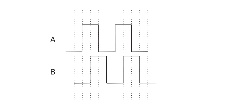
| PPR (Pulse Per Revolution)(A&B) | 25,50,100,200,256,300,400,500,512,1000,1024 A & B Pulse Lag each other by 90deg.(TTL) |
| Output (Voutput) | 0 to 5Vdc ( Redundant Output) (ideally 3% to 97% Vinput) |
| Index pulse Z | 1 pulse per RPM (TTL) |
Low Speed Quadrature Output

| Parameter | Results |
|---|---|
| Supply Voltage (Vsupply) | 5Vdc / 3.3Vdc |
| Supply Current | 20mA |
| Incremental Output | |
| Electrical Speed | 400RPM Max. |
| PPR (Pulse Per Revolution)(A&B) | 8,16,32,64,128,256,512,1024,2048 A & B Pulse Lag each other by 90deg.(TTL) |
| Output (Voutput) | 0 to 5Vdc ( Redundant Output) (ideally 3% to 97% Vinput) |
| Index pulse Z | 1 pulse per RPM (TTL) |
Serial Peripheral Interface Sensor
The RHSS12-XSPI is a Absolute encoder which acts as a slave and communicate with master micro controller as per the standard Protocol of SPI.
As per standard protocol of SPI RHSS12-XSPI communicate with master protocol when the MOSI pin is active high or 3FFF hex data is sent on the bus and the CS pin need to toggle from low to high for only one clock pulse.
RHSS12-XSPI communicate in 16 Bit of Transmission. After each cycle of communication it is compulsory to toggle CS pin from high to low.
RHSS12-XSPI has a provision of Dual Output first SPI communication and PWM mode of communication 14 Bit and 12 Bit of Resolution respectively.
Number of sensors can be connected in daisy chain mode of 4 wire or (n+3 wire connection). please contact Mr. Pavan Kinariwala(pavankinariwala@gmail.com) for more information on the same.
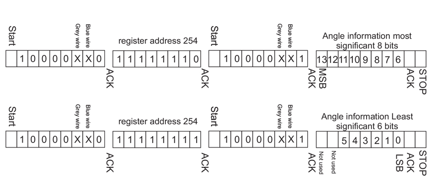
RHSS12-XSPI will communicate the angle information in below pattern.

| Parameter | Results |
|---|---|
| Input Voltage (Vinp) | 5Vdc / 3.3Vdc |
| Maximum clock Frequency | 50k Hz. |
| Digital pin Input / output level including address pins. VDD- 5Vdc (Vinp 5Vdc) VDD- 3.3Vdc (Vinp -- 3.3Vdc) |
1 -- VDD (5V or 3.3V) -0.7V 0 -- GND +0.4V |
| PWM Frequency | 1 Khz. |
Two Wire Communication sensor
The RHSS12-XSPI is a Absolute encoder which acts as a slave and communicate with master micro controller as per the standard Protocol of SPI.
As per standard protocol of SPI RHSS12-XSPI communicate with master protocol when the MOSI pin is active high or 3FFF hex data is sent on the bus and the CS pin need to toggle from low to high for only one clock pulse.
RHSS12-XSPI communicate in 16 Bit of Transmission. After each cycle of communication it is compulsory to toggle CS pin from high to low.
RHSS12-XSPI has a provision of Dual Output first SPI communication and PWM mode of communication 14 Bit and 12 Bit of Resolution respectively.
Number of sensors can be connected in daisy chain mode of 4 wire or (n+3 wire connection). please contact Mr. Pavan Kinariwala(pavankinariwala@gmail.com) for more information on the same.
RHSS12-XSPI will communicate the angle information in below pattern.

| Parameter | Results |
|---|---|
| Input Voltage (Vinp) | 5Vdc / 3.3Vdc |
| Maximum clock Frequency | 10k Hz. |
| Digital pin Input / output level including address pins. VDD- 5Vdc (Vinp --6 to 35Vdc or Vdc) VDD- 3.3Vdc (Vinp -- 3.3Vdc) |
1 -- VDD (5V or 3.3V) -0.7V 0 -- GND +0.4V |
| PWM Frequency | 1 Khz. |

DWDT-HE
- Draw wire linear transducer upto 150mm stroke with Contactless Hall's effect Absolute Encoder (Detachable)
- For Detailed Datasheet and more technical information please contact Mr. Pavan Kinariwala -9998700754

DWDT-P
- Draw wire linear transducer upto 1500mm stroke with Multiturn Wire Wound Potentiometer (Detachable)
- For Detailed Datasheet and more technical information please contact Mr. Pavan Kinariwala -9998700754

