
- The Rotary Miniature Angle Sensor is used to detect the angle of system which correspondence to the rotary motion of the shaft of the sensor
- The Output signal correspondence to 0 to 360deg. This full range is programmable based on requirement.
- Since the Product is based on Contactless Hall's effect Technology it has very long life.
- Endless Rotary sensor can be specially programmed to have 4,3 or 2 cycles in over revolution hence increasing the accuracy.
- For modern microcontrollers RHSS-12 is capable to give output in 0 to 3.3Vdc and to suppress the effect of Noise PWM output version is available.
VARIANTS
- 12 bit resolution 0 to 3.3Vdc Analog Ratio matric Output.
- 12 bit resolution 0 to 5Vdc Analog Ratio matric Output.
- 12 bit resolution 0 to 5Vdc Analog Ratio matric Dual Output.
- 12 bit resolution PWM Output.
- 14 Bit resolution in 16bit transmission SPI output.
- 14 bit resolution in 8bit transmission in I2C output.
- Upto 1024 PPR in one revolution incremental output.
- Sleeve bushing, Servo Mount, Flange Mount and Ball Bearing versions.
- Connectors or shielded cable available.
- IP 69k Protection available.
BENEFITS
- Non Contact Rotary Position Sensor based on Hall Effect Tenology.
- Accurate Linearity upto 1% F.S. or 0.5% F.S (on request)
- Extremely Long Life.
- Extremely Compact in Size.
- Angle programmable based on customer specific requirement.
- Short Circuit Protected. ( For 5Vdc and PWM output versions).
- vervoltage protected. ( For 5Vdc and PWM output versions).
- Reverse polarity protected. ( For 5Vdc and PWM output versions).
Mounting
For best performance of RHS-12 below points needs to be taken into consideration.
1) The hole in the panel should not be more than 9.5mm.
2) RHS-12 should be mounted with Star washer given along with the product and perpendicularity between the panel and axis of Sensor should be maintained.
Magnetic Cross Talk
If two RHS-12 units are to be installed closer than 2 inch (measured between the center of both shafts),a magnetic shield, such as a small steel plate should be installed in between to prevent one encoder from c a u s i n g s m a l l c h a n g e s i n r e p o r t e d p o s i t i o n t h r o u g h m a g n e t i c f i e l d c r o s s - t a l k .
Material
| Component | Material |
|---|---|
| Housing | Brass |
| Shaft | Stainless |
| Ball Bearing | Stainless |
Environment
| Parameter | Value |
|---|---|
| Operating Temperature | -40 to 75 deg (standard) -40 to 140 deg ( on request) |
| Storage Temperature | -40 to 75 degC |
| Vibration | 20g |
Ordering Information


For Detailed Drawing on Sensor with Servo Mount Please drop a E-mail on pavankinariwala@gmail.com
For SPI, I2C, Quadrature, Incremental and Redundant output version sensor comes along with Fly wire output.
Shaft Customization is possible.
Tight Motion of shaft is possible.
| Parameters | Ball Bearing | Sleeve Bushing |
|---|---|---|
| Starting Torque | 8 gms. cm | 150 gms. cm |
| Maximul Radial | Load 900 gms | 470 gms |
| Maximum Axial Load | Nil | Nil |
| Maximum Shaft Speed | 1500 RPM | 100 RPM |
| Bearing Life cycles | 20 X 10^6 @rated radial Load | 500 X 10^6 @rated radial Load |
| Weight of sensor | 12 gms | 12 gms |
| Shaft Dia | 2.95mm | 3.15mm or 6 mm or 6.3 mm |

| Parameter | Value |
|---|---|
| Supply Voltage (Vsupply) | 5Vdc(+/- 10%) or 3.3Vdc |
| Supply Current | 20mA |
| Response time | 50mS |
| Resolution | 12bit |
| Load Resistance | Minimum 10k ohms |
| Output (Voutput) | 3% to 97% Vsupply (Ratiomatric) |
| Linearity | 1% Independent Linearity ( Available 0.5% on request) |

| Parameter | Results |
|---|---|
| Supply Voltage (Vsupply) | 5Vdc(+/- 10%) or 3.3Vdc |
| Supply Current | 20mA |
| Frequency | 200Hz, 500Hz, 1K Hz or 2 Khz based on requirement |
| Resolution | 12bit |
| Output (Voutput) | 0% to 100% duty Cycle |
| Linearity | 1% Independent Linearity ( Available 0.5% on request) |

The Graph is just for indicative purpose. Offset between Output 1 and Output 2 can be change or made
| Parameter | Results |
|---|---|
| Supply Voltage (Vsupply) | 5Vdc |
| Supply Current | 50mA |
| Electrical Angle | Default 359.92 deg. (Customization possible) |
| Response Time | 1kHz |
| Resolution | 12bit |
| Output (Voutput) | 0 to 5Vdc ( Redundant Output) (ideally 3% to 97% Vinput) |
| Load Resistance | Minimum 10K Ohms |
| Linearity | 1% Independent Linearity ( Available 0.5% on request) |

| Parameter | Results |
|---|---|
| Supply Voltage (Vsupply) | 5Vdc / 3.3Vdc |
| Supply Current | 20mA |
| Incremental Output | |
| Electrical Speed | 10000RPM Max. |
| PPR (Pulse Per Revolution)(A&B) | 25,50,100,200,256,300,400,500,512,1000,1024 A & B Pulse Lag each other by 90deg.(TTL) |
| Output (Voutput) | 0 to 5Vdc ( Redundant Output) (ideally 3% to 97% Vinput) |
| Index pulse Z | 1 pulse per RPM (TTL) |

| Parameter | Results |
|---|---|
| Supply Voltage (Vsupply) | 5Vdc / 3.3Vdc |
| Supply Current | 20mA |
| Incremental Output | |
| Electrical Speed | 400RPM Max. |
| PPR (Pulse Per Revolution)(A&B) | 8,16,32,64,128,256,512,1024,2048 A & B Pulse Lag each other by 90deg.(TTL) |
| Output (Voutput) | 0 to 5Vdc ( Redundant Output) (ideally 3% to 97% Vinput) |
| Index pulse Z | 1 pulse per RPM (TTL) |
The RHSS12-XSPI is a Absolute encoder which acts as a slave and communicate with master micro controller as per the standard Protocol of SPI.
As per standard protocol of SPI RHSS12-XSPI communicate with master protocol when the MOSI pin is active high or 3FFF hex data is sent on the bus and the CS pin need to toggle from low to high for only one clock pulse.
RHSS12-XSPI communicate in 16 Bit of Transmission. After each cycle of communication it is compulsory to toggle CS pin from high to low.
RHSS12-XSPI has a provision of Dual Output first SPI communication and PWM mode of communication 14 Bit and 12 Bit of Resolution respectively.
Number of sensors can be connected in daisy chain mode of 4 wire or (n+3 wire connection). please contact Mr. Pavan Kinariwala(pavankinariwala@gmail.com) for more information on the same.
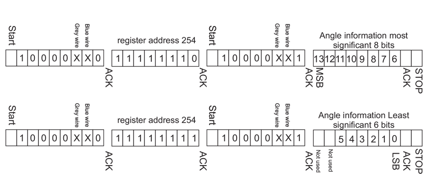
RHSS12-XSPI will communicate the angle information in below pattern.

| Parameter | Results |
|---|---|
| Input Voltage (Vinp) | 5Vdc / 3.3Vdc |
| Maximum clock Frequency | 50k Hz. |
| Digital pin Input / output level including address pins. VDD- 5Vdc (Vinp --> 5Vdc) VDD- 3.3Vdc (Vinp --> 3.3Vdc) |
1 --> VDD (5V or 3.3V) -0.7V 0 --> GND +0.4V |
| PWM Frequency | 1 Khz. |
The RHSS12-XSPI is a Absolute encoder which acts as a slave and communicate with master micro controller as per the standard Protocol of SPI.
As per standard protocol of SPI RHSS12-XSPI communicate with master protocol when the MOSI pin is active high or 3FFF hex data is sent on the bus and the CS pin need to toggle from low to high for only one clock pulse.
RHSS12-XSPI communicate in 16 Bit of Transmission. After each cycle of communication it is compulsory to toggle CS pin from high to low.
RHSS12-XSPI has a provision of Dual Output first SPI communication and PWM mode of communication 14 Bit and 12 Bit of Resolution respectively.
Number of sensors can be connected in daisy chain mode of 4 wire or (n+3 wire connection). please contact Mr. Pavan Kinariwala(pavankinariwala@gmail.com) for more information on the same.
RHSS12-XSPI will communicate the angle information in below pattern.
| Parameter | Results |
|---|---|
| Input Voltage (Vinp) | 5Vdc / 3.3Vdc |
| Maximum clock Frequency | 10k Hz. |
| Digital pin Input / output level including address pins. VDD- 5Vdc (Vinp --> 6 to 35Vdc or Vdc) VDD- 3.3Vdc (Vinp --> 3.3Vdc) |
1 --> VDD (5V or 3.3V) -0.7V 0 --> GND +0.4V |
| PWM Frequency | 1 Khz. |

Standard 6.3mm shaft dia

Ball Bearing version with 3mm shaft dia

Ball Bearing Servo Mount version with 3mm shaft dia
