http://wowslider.net/ by WOWSlider.com v8.7
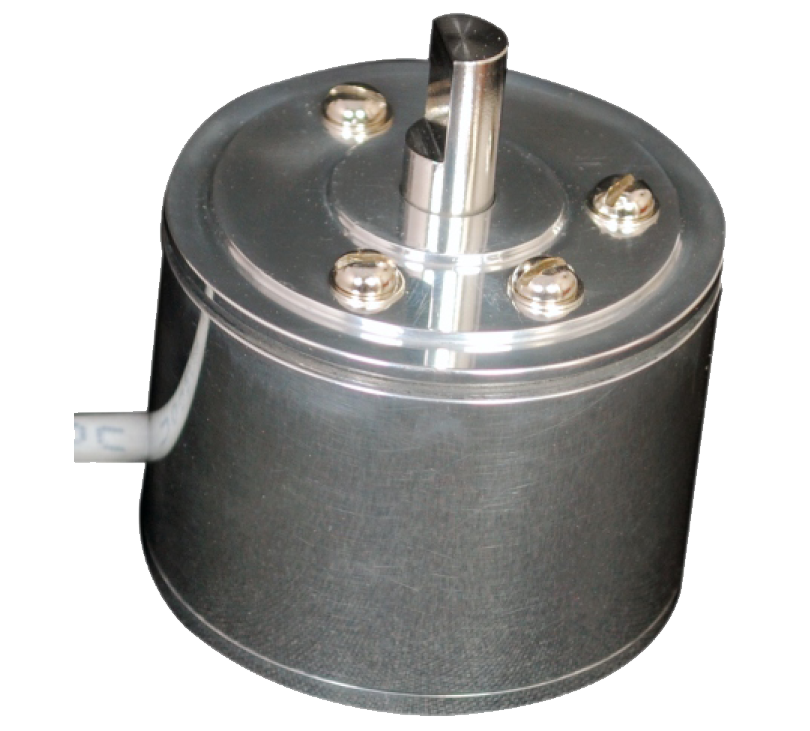
- Rotary Rugged Sensor is a transducer to detect the angle / speed of the system which correspondence to the rotary motion of the shaft.
- Rotary Rugged Sensor is based on contactless Magnetic technology and hence has a very long life
- This Transducer can be customised in several ways to have different Electrical angle, Voltage Output, Current Output, Digital Communication signals such as SSI, SPI, I2C or Incremental Output.
- Rotary Rugged Sensor housing and Sensor Shaft can be modified based on the requirement
- This Transducer has a Optional of Having Span and Offset settable with TWO trim pots given at the back of the system for certain variant.
- The Protection class of the standard sensor is IP65 However the same can be increased subject to the requirement of the user.
Mounting
- There are two types of Mounting Provision available. 1)Servo Mount: Servo mount Groove is available to fix the Transmitter for which 40mm of hole in a plate of minimum 2 mm thick need to be made along with clamp to fix the transmitter. EMC48 encoder mounting clamps are available for the same. 2) Top Mount: 3 M3 Threaded Screws at 120deg apart in a PCD of 30mm dia is given with 5mm dip. For which 20mm of hole in a plate of minimum 1mm thick is necessary.
- To have the best performance of the sensor the Radial load on the sensor should be minimum. To elaborate the Misalignment between the Axis of the transmitter and Shaft should be nil.
Material
| Part | Description |
|---|---|
| Housing | Alluminum |
| Shaft | S.S |
| O-Ring | Rubber |
| Cable | Uniqa Make 3 core 0.25sq.mm shielded |
Mechanical characteristics
| Parameters | Results |
|---|---|
| Maximum Radial Load on shaft | 1kg |
| Maximum Axial Load on shaft | 1 kg |
| Maximum Mechanical Speed | 10000RPM |

| Parameter | Value |
|---|---|
| Supply Voltage (Vsupply) | 5Vdc / 6-35Vdc / 24 Vdc |
| Supply Current | 100mA |
| Response time | 50mS |
| Load Resistance | Minimum 10k ohms |
| Output (Voutput) | 3% to 97% Vsupply (Ratiomatric) For 5Vdc Supply. 0 to 5Vdc / 0 to 10Vdc /4-20mA (For 24Vdc input or 15-35Vdc |
| Linearity | 1% Independent Linearity ( Available 0.5% on request) |
| Parameter | Results |
|---|---|
| Supply Voltage (Vsupply) | 6-35Vdc input |
| Supply Current | 20mA |
| Frequency | 2 Khz |
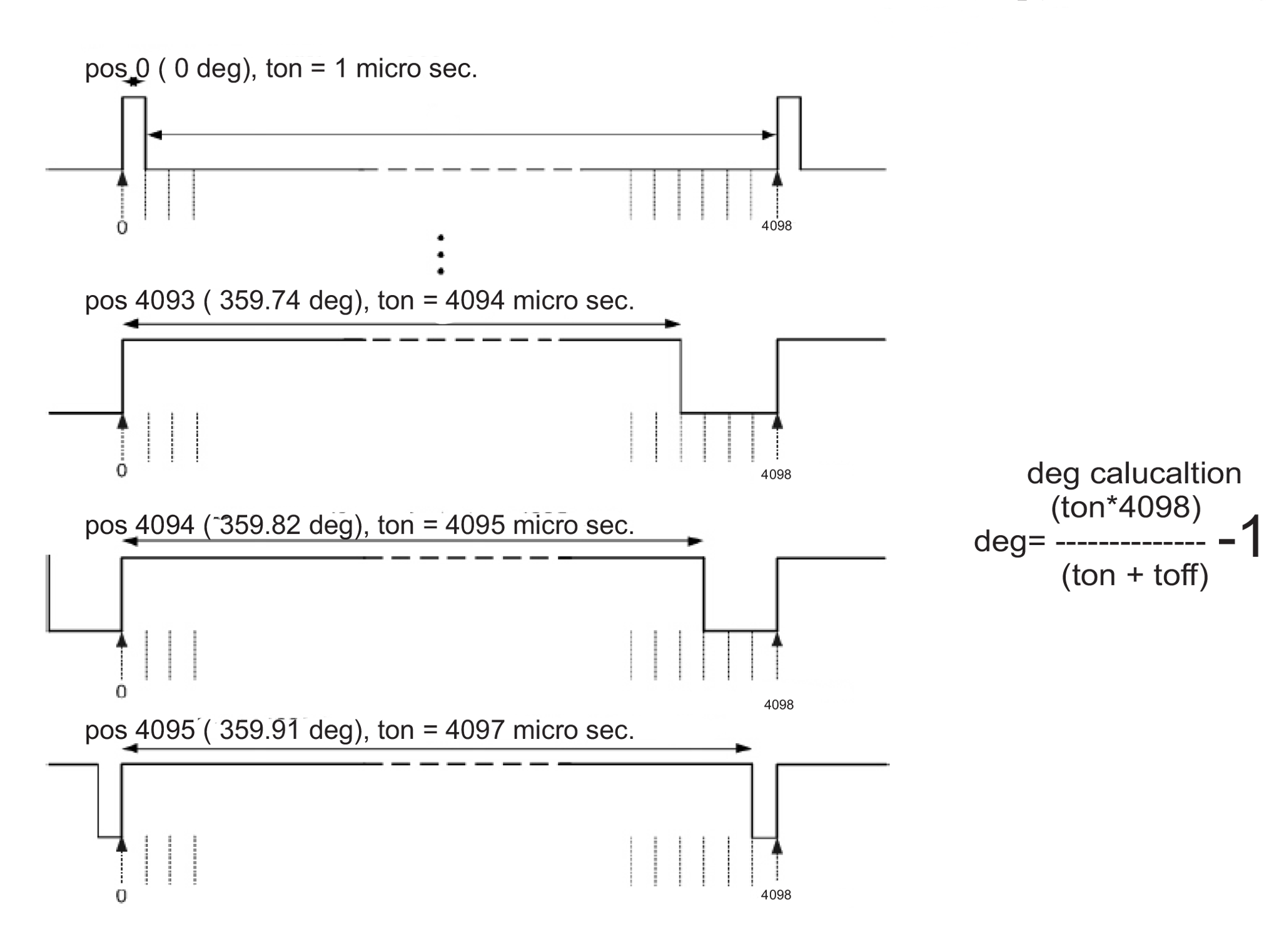
| Resolution | 12bit |
| Output (Voutput) | 0% to 100% duty Cycle |
| Linearity | 1% Independent Linearity |

| Parameter | Results |
|---|---|
| Supply Voltage (Vsupply) | 5Vdc/ 6-35Vdc / 24 Vdc |
| Frequency | 20Hz |
| Output (Voutput) | 3% to 97% Vsupply (Ratiomatric) For 5Vdc Supply. 0 to 5Vdc / 0 to 10Vdc /4-20mA (For 24Vdc input or 15-35Vdc input |
| Linearity | 1% Independent Linearity ( Available 0.5% on request) |
| Parameter | Results |
|---|---|
| Supply Voltage (Vsupply) | 5Vdc or 3.3Vdc or 24Vdc or 6 to 35Vdc |
| Supply Current | 20mA |
| Electrical Speed | 10000RPM Max. |
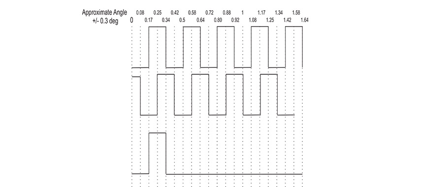
| PPR (Pulse Per Revolution)(A&B) Prgrammable using | 125,50,100,200,256,300,400,500,512,1000,1024 A & B Pulse Lag each other by 90de |
| Index pulse Z | 1 pulse per RPM |
| Signal Type | NPN open Collector. / PNP Open Collector / 5VTTL / 3.3V TTL |
| Sourcing Current | 5mA |
| Maximum Electrical Speed | 15000RPM |

| Parameter | Results |
|---|---|
| Supply Voltage (Vsupply) | 5Vdc / 3.3Vdc |
| Supply Current | 20mA |
| Incremental Output | |
| Electrical Speed | 400RPM Max. |
| PPR (Pulse Per Revolution)(A&B) | 8,16,32,64,128,256,512,1024,2048 A & B Pulse Lag each other by 90deg.(TTL) |
| Output (Voutput) | 0 to 5Vdc ( Redundant Output) (ideally 3% to 97% Vinput) |
| Index pulse Z | 1 pulse per RPM (TTL) |
- The RHSS48-635SPI is a Absolute encoder which acts as a slave and communicate with master micro controller as per the standard Protocol of SPI.
- RHSS48-635SPI communicate in 16 Bit of Transmission
- As per standard protocol of SPI RHSS48-635SPI communicate with master protocol when the MOSI pin is active high or 3FFF hex data is sent on the bus and the CS pin need to toggle from low to high for only one clock pulse.
- After each cycle of communication it is compulsory to toggle CS pin from high to low.
- RHSS48-635SPI has a provision of Dual Output first SPI communication and PWM mode of communication 14 Bit and 12 Bit of Resolution respectively.
- Number of sensors can be connected in daisy chain mode of 4 wire or (n+3 wire connection). please contact Mr. Pavan Kinariwala (pavankinariwala@gmail.com) for more information on the same.

| Parameter | Results |
|---|---|
| Digital pin Input / output level including address pins. VDD- 5Vdc (Vinp --> 5Vdc) VDD- 3.3Vdc (Vinp --> 3.3Vdc) |
1 --> VDD (5V or 3.3V) -0.7V 0 --> GND +0.4V |
- The RHSS22-635I2C is a Absolute encoder which acts as a slave and communicate with master micro controller as per the standard Protocol of I2C. It is also known as Two Wire Communication.
- RHSS22-635I2C communicate in 8 Bit of Transmission.
- As per standard Protocol each slave (RHSS22-635I2C) has a Slave address of 7 bit which is being made of two Address Pin 1 and 2 while the remaining 4 bits are always 0 and MSB being 1. Address pin 1 and 2 are Least significant bit of Address. Hence we can use maximum of 4 such sensors in a Daisy chain mode of communication with slave address as 6555556pcp 6555555pcp6555566pcp6555565r
- RHSS22-635I2C has a provision of Dual Output first I2C communication and PWM mode of communication 14 Bit and 12 Bit of Resolution respectively.
- RHSS22-635I2C communicates the angle information in two cycles. By sending the register address 254 and 255. To have the complete angle information we need to eliminate two most significant bit (6 and 7) of the data byte we receive after sending register address 255.

| Parameter | Results |
|---|---|
| Input Voltage (Vinp) | 6 to 35Vdc / 5Vdc / 3.3Vdc |
| Maximum clock Frequency | 10k Hz. |
| Digital pin Input / output level including address pins. VDD- 5Vdc (Vinp --> 6 to 35Vdc or 5Vdc) | 1 --> VDD (5V or 3.3V) -0.7V 0 --> GND +0.4V |

incremental encoder analog with Absolute encoder